Air Terminals
![]() Used to place grilles
and diffuser, as well as plenums. These fittings add air terminals to a route.
Used to place grilles
and diffuser, as well as plenums. These fittings add air terminals to a route.

Selecting a fitting from the ribbon panel activates the Place Component settings dialog, where you can manage the schema parameters (DG instance properties). Also, the contextual Placement tab appears on the ribbon, that provides placement settings options for the currently selected fitting.
The generic placement settings, along with the unique set of dimensional and data parameters from the datagroup system provide the core workflow used to accurately position mechanical components within a system.
Component categories
Diffusers are used in HVAC systems as part of room air distribution subsystems to deliver both conditioning and ventilating air by evenly distributing the flow of air, in the desired directions. Diffusers are easily placed to the outlets of ducts of any shape simply with the help of AccuSnap. Diffuser diameter gets adjusted with the dimension of the duct.
Grille is a class of air terminals. Most HVAC grilles are used as return or exhaust air inlets to ducts, but some are used as supply air outlets. Diffusers and nozzles, are, for example, used as supply air outlets too. Registers are a type of HVAC grille that also incorporates an air damper.
Plenum boxes are used for supply and exhaust of air through diffusers and grilles. The plenum box ensures a continuous flow to the diffuser, and plenum boxes equipped with dampers create the possibility of adjusting the diffuser on an individual level. Acoustic insulation in Plenum boxes contributes to the sound attenuation inside the box. This way the noise from the air flow inside the air duct system and the sound from room to room is reduced. The multi-port plenum boxes allow the user to configure the component to include multiple duct connection ports for all duct shapes and locations on the plenum.
Jet nozzles are used for preference where the supply air from the diffuser has to travel a large distance to the occupied zone. This is the case in large rooms (halls, assembly rooms etc.), particularly when the distribution of air via ceiling diffusers is not possible or not practical. Here jet diffusers are arranged in the side wall areas. When the temperature difference between the supply air and the room air changes, the supply air stream is deflected upwards (warm air) or downwards (cold air). The direction of the supply air flow is also affected by other influences such as local convection effects or draughts within the room.
These components are simply be snapped and placed at the end of duct in a required capacity. Diffusers and Plenum boxes' three categories are based on their shape type. They are available for ceiling, wall and floor orientations. Diffusers employ one of the seven grille types. Jet nozzle diffusers having rear duct connection element with a peripheral flange and optional spigot or a saddle connector with flange provides options for fixing to the side of rectangular or circular ducts. To ease the simultaneous mounting of different jet diffusers side by side on a wall or a duct, the possibility is given to get two or three jet nozzles pre-mounted on a single panel. The panel is then fixed onto a wall or other panel.
Diffusers share many of the common Properties.
Grilles categories are based on their shape type. They are rectangular, round, and a oval flat. Other than mesh and 4-way, the grille type sets the grilles configuration to bar, bar slot, star, and rect/round slot. The vertical and horizontal bars form a desired mesh structure in a grille. The grilles share most of the common Properties.
Notable Properties
- Connection End Type – The end conditions of fittings are set to flange, male or female connections with full dimensional control by setting the End Type property. Also, the two ends are independent, and may have different connections. For example, the value fl-2;fe-.13 creates a flange at End1 with size 2, and a female connection at End2 with a clearance of .13.
- Connection- Left/Right Side – In addition to 4 Number of Ports two additional ports can be configured to include on the sides of plenum; one on left and another on the right side.
- Grille Type – Grille configurations are set to one of the seven types. The grilles are – mesh, bars, bar slots, 4-way, star rectangular slot and round slots.
- Outlet Pressure (in. wg) – Similar to the Air Flow Rate (CFM), the value set for the outlet pressure property of the terminal units is taken in calculation Duct Sizing utility where the grilles are used as openings to the route.
- Throw
Pattern – The orientation and number of throw patterns are set to
one of the five types – one way, two way, two way corner, three way and four
way.
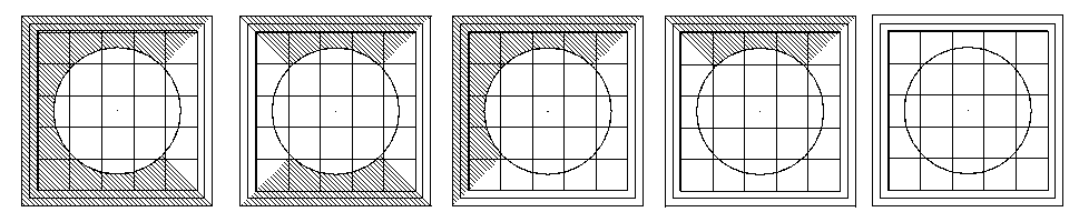
Diffusers top view illustrating the Throw Pattern set, from left to right to: One Way, Two Way, Two Way Corner, Three Way and Four Way.
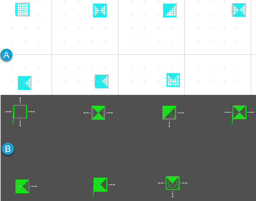
- When set the throw pattern forms a hatching pattern that controls airflow direction out of the diffuser enclosure. The effect on diffusers graphically is a hatching pattern that represents baffling designed to control airflow direction out of the diffuser enclosure.
- The throw patterns are oriented to the global coordinates. That is, they do not rotate automatically if they are placed close to a wall. Rotating diffusers manually after placement help in positioning the throw patterns to optimum effect in room air mixing.
- The effect on diffusers graphically is a hatching pattern that represents baffling designed to control airflow direction out of the diffuser enclosure. When extracted the diffusers with throw patterns are clearly seen representing appropriate hatch patterns.
Notable Property Options
Manufacturer Catalog – Edits the current Catalog having standard properties assigned to the grille, that had set in the Properties via selecting a catalog name.
Auto Size – Opens the Auto Size Options dialog where the options allow to set the grille type, grille dimensions including the slots. The values in autosize controls the symmetry of the grille by re-sizing it in four ways.